CN2300 Series
1/4 DIN Ramp/Soak Advanced Temperature/Process Controller
スクロールダウンし、全ラインアップをご覧ください
-
Graphical LCD Text Display (Red/Green)
-
Front Mounted USB Interface Port
-
64 Independent Programs
-
255 Segments per Program
-
Universal Inputs
-
Autotune PID
-
Modular Isolated Control Outputs
-
Data Logging Models (Data, Alarms and Events)
-
RS-485 Communications (Optional)
-
Software with configuration cable (Optional)
-
Alarm Functions
-
5 Language Options (English, French, German, Italian, Spanish)
商品説明
This product series is no longer available. For potential replacements please see
CN-4000-Series
Please consult an application engineer for a more specific recommendation.
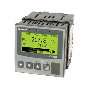
The CN2300 Series 1/4 DIN profile controller with
graphic/text LCD display and USB interface is an
affordable temperature and process controller with
advanced functionality including datalogging options.
Designed to improve user efficiency many features
are integrated to reduce commissioning time, simplify
operation and minimize maintenance downtime.
Features include graphic easy to read backlit LCD
display, dual color screen (green/red), multi-language
option, custom splash-screen on startup (bitmap file),
alarm status view, on screen trend view, LEDs to
indicate heat, cool, autotuning and alarm.
Easy setup wizard (via front keys) for quick configuration of inputs,
alarms, outputs, communications and real-time clock.
Universal input for thermocouple, RTD’s and linear DC
process signals (mA, mV or V). Flexible modular output
options include mechanical relay, dc Pulse, AC SSR
triac and linear outputs. Select to precisely match the
process, digital input (2 max) for setpoint selection,
profile control, datalogging start/stop, control output
enable/disable or auto/manual control. The CN2300
series features configurable menus (using optional software
with cable for configurating units via RJ11 configuration
socket), USB port for local upload/download of configuration
files and download logged data to or from a USB memory stick.
This allows easy configuration of multiple instruments by
copying from one unit to another.
Profile feature includes 255 segments to allocate freely
in up to 64 programs. Programs include ramp, soak,
hold, loop or jump to other profile. User defined text
profile name, delayed or real-time day/time profile start,
and up to 5 event outputs.
The CN2300 datalogging models include historic
process data for analysis or reporting, and export data
files via front USB or optional communications, and
will log process values, setpoints or alarms (including
minimum, maximum and average), with logging
intervals from 1s to 30m. Many options include analog
remote setpoint, built in 24 Vdc transmitter power
supply, and graphical software.
SPECIFICATIONS
Process Input
Sampling Rate: 10 per second
Resolution: 16 bits, always four times better than display resolution
Impedance: >10M Ω resistive, except DC mA (5 Ω) and V (47k Ω)
Temperature Stability: Error <0.01% of span per °C change in ambient temperature
Supply Variation: Supply voltage influence negligible within supply limits
Humidity Influence: Negligible if non-condensing
Process Display: Displays up to 5% over and 5% under span limits Process Variable Input Offset: Reading adjustable ± Controller Span. +ve values added to Process Variable, -ve values subtracted from Process Variable
Sensor Break Detection:
Thermocouple and RTD: Control goes to pre-set power value
High and Sensor Break: Alarms activate
Linear (4 to 20 mA, 2 to 10V and 1 to 5V only): Control goes to pre-set power value
Low and Sensor Break: Alarms activate
Isolation: Isolated from all outputs (except SSR driver) at 240 Vac
DC Calibration: ±0.1% of full range, ±1LSD
DC Input Multi-Point Linearization: Up to 15 scaling values can be defined anywhere between 0.1 and 100% of input
Supported RTD Types and Ranges: 3-Wire,
PT100: -199 to 800°C (-328 to 1472°F)
NI120: -80 to 240°C (-112 to 464°F) Optional decimal place can be displayed up to 999.9°C/F
RTD Excitation: Sensor current 150ìA ±10%
Lead Resistance: <0.5% of span error for max 50 Ω per lead, balanced
Accuracy: ±0.25% of input range 1 LSD
Sampling Rate: 4 per second
Resolution: 16 bits
Impedance: >10M resistive, except DC mA (10 Ω) and V (47k Ω)
Sensor Break Detection: 4 to 20mA, 2 to 10V and 1 to 5V ranges only. Control goes to pre-set power value if Aux Input is the active setpoint source.
Isolation: Reinforced safety isolation from outputs and inputs (except to Digital Input B)
Auxiliary Input Scaling: Scalable as remote setpoint (RSP) input between -1999 and 9999, constrained within setpoint limits
Digital Inputs
Volt-Free Contacts (or TTL): Open contacts (>5000or 2 to 24 Vdc signal = Logic High Closed contacts) (<50 or -0.6 to +0.8 Vdc signal = Logic Low)
Isolation: Reinforced safety isolation from inputs and other outputs
Digital Input Sensitivity: Edge sensitive; Requires high-low or low-high transition to change function; Response within <0.25 second
Outputs
Isolation: Reinforced safety isolation from inputs and other outputs. (Common specification for all output types)
Single Relay
Type and Rating: Single pole single throw (SPST), 2A resistive at 120/240 Vac
Lifetime: >500,000 operations at rated voltage/current
Dual Relay
Type and Rating: Single pole single throw (SPST), 2A resistive at 120/240 Vac (dual relay modules have shared common)
Lifetime: >200,000 operations at rated voltage/current
Quad Relay
Type and Rating: Single pole single throw (SPST), 2A resistive at 120/240 Vac (dual relay modules have shared common)
Lifetime: >500,000 operations at rated voltage/current
dc Pulse
Drive Capability: SSR driver voltage >10V into 500 Ω minimum
Triac
Operating Voltage: 20 to 280Vrms (47 to 63Hz)
Current Rating: 0.01 to 1A (full cycle rms on-state @ 25°C); de-rates linearly above 40°C to 0.5A @ 80°
Linear DC
Ranges: 0 to 5, 0 to 10, 1 to 5, 2 to 10V and 0 to 20, 4 to 20 mA (selectable) with 2% over/under-drive when used for control outputs
Resolution: 8 bits in 250mS (10 bits in 1s typical, >10 bits in >1s typical)
Accuracy: ±0.25% of range, (mA @ 250, V @ 2k) Degrades linearly to ±0.5% for increasing burden (to specification limits)
Transmitter PSU
Power Rating: 24 V nominal (19 to 28 Vdc) into 910 Ω minimum resistance. (Option to use DC Linear output as 0 to 10V stabilised PSU)
Isolation: Reinforced safety isolation from inputs and other outputs
Communications
PC Configuration
Connection: RS232 via PC Configurator Cable to RJ11 socket under case
Isolation: Not isolated from input or SSR Driver outputs. For bench configuration only
RS485
Connection: Locates in Option Slot A. Connection via rear terminals
Protocol: Modbus RTU
Slave/Master Mode: Slave address range 1 to 255 or Setpoint master mode
Supported Speeds: 4800, 9600, 19200, 38400, 57600 or 115200 bps
Data Type: 8 data bits and 1 stop bit. Odd, even or no parity
Isolation: 240V reinforced safety isolation from all inputs and outputs
Ethernet
Connection: Locates in option slot A, connection via RJ45 connector on top of case
Protocol: Modbus TCP (slave only)
Supported Speed: 10BaseT or 100BaseT
Isolation: 240V reinforced safety isolation from the supply, inputs and outputs (except SSR Drivers) Loop Control
Tuning Types: Pre-Tune, Auto Pre-Tune, Self-Tune or Manual Tuning
Proportional Bands: Primary and secondary (e.g. heat and cool) 0.5% to 999.9% of input span in 0.1% increments, or On/Off control
Automatic Reset: Integral Time Constant, 1s to 99min 59s and OFF
Rate: Derivative time constant, 1s to 99 min 59s and OFF
Manual Reset: Bias 0 to 100% (-100% to +100% primary and secondary)
Deadband/ Overlap: -20% to +20% of primary + secondary proportional band
ON/OFF Differential: 0.1% to 10.0% of input span
Auto/Manual Control: Selectable with “bumpless” transfer when switching between automatic and manual control
Cycle Times: Selectable from 0.5s to 512s
Setpoint Ramp: Ramp rate selectable 1 to 9999 LSDs per hour and infinite
Alarms
Alarm Types: Up to 5 alarms selectable as process high, process low, band, deviation, rate of signal change (per minute), sensor/input break, loop alarm. Band and deviation (high or low) alarm values are relative to the current setpoint value.
Alarm Hysteresis: A deadband from 1 LSD to full span (in display units) for Process, Band or Deviation Alarms. Rate of Change Alarm hysteresis is the shortest time (1 to 9999 seconds) the rate of change must be above the threshold for the alarm activate, or fall below the threshold to deactivate.
Note: If the duration is less than this time, the alarm will not activate no matter how fast the rate of rise. Combination Alarm
Outputs: Logical OR of alarms 1 and 2, 1 to 3, 1 to 4 or 1 to 5. Logical AND of alarms 1 to 5 with Profiler Events 1 to 5 Operating Conditions (for Indoor Use)
Temperature:
Operating: 0 to 55°C (0 to 131°F)
Storage: -20 to 80°C (-4 to 176°F)
Relative Humidity: 20 to 95% non-condensing
Supply Voltage and Power:
Mains Versions: 100 to 240 Vac ±10%, 50/60Hz, 20VA
Low Voltage Versions: 20 to 48VC 50/60Hz 15VA or 22 to 65 Vdc 12W
Environmental
Front Panel Sealing: To IP66 (IP65 front USB connector) IP20 behind the panel
Display
Display Type: 160 x 80 pixel, monochrome graphic LCD with a dual colour (red/green) backlight
Display Area: 66.54 W x 37.42 mm H (2.62 x 1.65")
Display Characters: 0 to 9, a to z, A to Z, plus ( ) - and _
Trend View: 120 of 240 data points shown in a scrollable window. Data is not retained when power turned off or if time base is changed.
Trend Data: Any active alarm plus PV (solid) and SP (dotted) at sample time or Max/Min PV between samples (candlestick graph)
Trend Sample Rate: 1; 2; 5; 10; 15; 30 seconds or 1; 2; 5; 10; 15; 30 minutes
Additional Communications Options - USB*
Connection: Locates in Option Slot C. Connection via front mounted connector
Protocol: USB 1.1 or 2.0 compatible; mass storage class
Supply Current: Up to 250mA
Targeted Peripheral: USB Memory Stick.
Isolation: Reinforced safety isolation from all inputs and outputs.
* Not used for PC configuration
Data Recorder
Recording Memory: 1Mb non-volatile flash memory. Data retained when power is turned off.
Recording Interval: 1; 2; 5; 10; 15; 30 seconds or 1; 2; 5; 10; 15; 30 minutes
Recording Capacity: Dependant on sample rate and number of values recorded; Two values can be recorded for up to 7 days at 10s intervals. More values or faster sample rates reduce the maximum duration.
RTC Battery Type: CR 1616 3V Lithium. Clock runs for >1 year without power
RTC Accuracy: Real Time Clock error <1second per day
Profiler
Profile Limits:
Number of profiles: 64 maximum
Total Number of Segments (All Programs): 255 maximum
Loop Back: 1 to 9999 loops back to specified segment
Profile Cycling: 1 to 9999 or Infinite repeats per profile
Sequence Repeats: 1 to 9999 or Infinite repeats of joined profile sequences
Segment Types: Ramp up/down over time, ramp rate up/ down, step, dwell, hold, join a profile, end or repeat sequence then end
Timebase: hh:mm:ss (hours, minutes and seconds)
Segment Time: Maximum segment time 99:59:59 hh:mm:ss; Use loop-back for longer segments (e.g. 24:00:00 x 100 loops = 100 days).
Ramp Rate: 0.001 to 9999.9 display units per hour
Hold Segment Release: release with key press, at time of day or digital input
Start From: 1st segment starts from current setpoint or current input value
Delayed Start: After 0 to 99:59 (hh:mm) delay, or at specified day(s) and time
Abort Action: keep last profile setpoint, use controller setpoint or control outputs off
Power/Signal Loss Recovery: Continue profile, restart profile, keep last profile setpoint, use controller setpoint or control outputs off
Auto-Hold: Hold if input >Band above and/or below SP for each segment
Profile Control: Run, manual hold/release, abort or jump to next segment
Segment Events: Events turn on for the duration of the segment. For End Segments, the event state persists until another profile starts, the user exits from profiler mode, or the unit is powered down
Dimensions
Front Bezel Size: 1/4 DIN; 96 x 96 mm (3.78 x 3.78")
Mounting: Plug-in with panel mounting fixing strap
Panel Cut-Out Size: 92 x 92 mm (3.62 x 3.62") (maximum panel thickness 6.0 mm [0.236"])
Depth Behind Panel: 117 mm (4.61")
Ventilation: 20 mm (0.787") gap required above, below and behind
Weight: 0.65 kg (1.43 lb) maximum
Terminals: Screw type (combination head)
製品マニュアル:
ダウンロード
CN2300 Series - Graphic Controllers
ダウンロード
CN2300 Series - Graphical 1/4 DIN Process Controller
ダウンロード
CN2300 Series - Graphical 1/4 DIN Profiler and Recorder