フリーダイヤル 0120-769-103
Emailjpesales@dwyeromega.com

24-Channel Ethernet Data Logger with Embedded Web Server

OM-240

Ethernet Data Logger with Embedded Web Server | OM-240

Ethernet Data Logger with Embedded Web Server

¥655,525 OM-240

1 year warranty CE
  • Omega Enterprise Gateway Compatible
  • 24 Differential, Independent Analog Input Channels, 2 Digital Inputs and 1 Digital Output
  • On-Board Web Server for Setup, Data View, and Diagnostic
  • Independent Thermocouples, PT100/200/500/1000, NTC, mV, mA, mV/V, Vibrating Wire
  • Integrated Sensors Power Supply, Independent for Each Channel: 5V, 10V, 20V, 24V DC
  • Alarms Setup for Each Channel (Min, Max, Derivate)
  • View Data in Real Time or Store to 2 GB Internal Memory
  • Modbus TCP, Ethernet, RS485, RS232 and USB Connections
  • Thermocouple Break Detection to Offer Real Time Alert to Customer
  • SMS and E-mail Alerts/Alarms & Available GPRS Modem
  • Expandable Up to 384 Channels with Multiplexers
データロガー - 関連する商品を探す
(見つからない場合はカスタマーサービスにご連絡ください)

商品説明

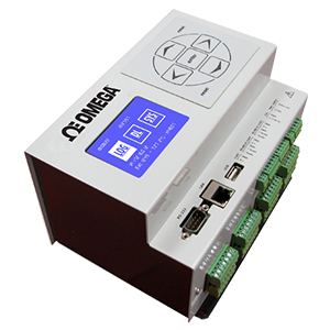
OM-240 is a versatile, high accuracy “smart” data acquisition system. It provides 24 differential analog inputs, individually configured.


OM-240 Overview
The Data Logger can be used in a wide range of applications, including HVAC, Oil and Gas, Water Quality, Energy and Building Monitoring. Using OM-240 requires no additional configuration/analysis software package, as it is provided by an Embedded Web Server. Only a standard Web Browser (Firefox recommended) for configurations and data view. Logged Data is ready to be shown in a graphic “real time” mode (License required) or exported in a CSV file. Channel expansion provided by multiplexers. There are 8 terminal blocks (each terminal block can handle up to 3 sensors). The OM-240 is designed to work with 2 to 6-wire sensors. You can connect 2-wire sensors on each channel and read 24 sensors, or 4-wire sensor and read 12 channels. The system will order sensors depending on how many wires they use, placing 6 wires sensors first, 4 wires in the middle, and 2 wires last.


OM-240 Charting
Once software configuration is done, clicking on “Wiring scheme” button on the web interface near the sensors will show how to connect the chosen sensor to the block physically. It shows “relative” position, so if you start connecting sensors from the first, you will not have to leave “unused” positions (except for the ground connection of every block, if not used). Multiplexers are needed if the total “wires” from sensors exceeds the 48 provided by the OM-240.

Applications including Oil/Gas Pipeline Monitoring, Building/Bridge Structure Health Monitoring, Engine Thermal Mapping Testing, Data Center Environmental Monitoring, and Energy Farm Monitoring, and etc.

Specifications
Weight 980 g (2.16 lb)
Dimensions: 231 L x 138 W x 117 mm H (9.09 x 5.43 x 4.61”)
Material: Plastic and metal
Wiring: Removable screw terminal connectors
MEASUREMENT RATE
Analog Initialization (±10V range):
    Maximum Speed: 1.70 sec
    Standard Speed: 7.10 sec
Instrument Warm-Up: Depends on sensor configuration
Measurement (±10V range:
    Maximum Speed: 80 ms
    Standard Speed: 1.57 sec
Notes: Times indicated are not valid for vibrating wire measures Init analog phase is made only once before measurement cycle
Measure Frequency Selectable (Global or for Each Channel): 1 second up to 1 week
ADC: 24-bit (22 true bit) differential analog-to-digital converters, 5SPS to 1000SPS, 0-24 average function, auto-calibration and auto-range
CPU and MEMORY
Processor: ARM Cortex-M3 MCU with 1 MB Flash, 120 MHz CPU, ART Accelerator, Ethernet
RAM Memor 1 Mbyte RAM
Mass Storage: 2 GB SD card for data (about 5 Mega data points) and Web pages
Clock Accuracy: RTC (real time clock with battery back-up) temperature compensated
On-Board Sensors: Temperature (accuracy ±1%), measured inside the datalogger
Switched Output Power Supply: The voltage ‘V OUT’ is switched on and off under program control. V OUT is the unregulated input power supply ‘V IN’ (2 A Max)
SOFTWARE and FIRMWARE
Web Server on Board: (independent OS platform)
Acquisition Time Interva: Selectable from 1 second up to 1 week (depends on the number of channels acquired)
FTP client: To send data/alarms on an FTP server (SFTP not supported)
MAIL to send data/alarm: To max 5 email address (SMTPS / SSL not supported)
SMS to Send Alarms: To max 5 telephone numbers
Data Download: (measure, logs) in .csv file (compatible with Microsoft Excel)
Virtual Channels Management: For Math operations between channels

OM-240 Thermocouple Input Setup
ANALOG INPUTS
Thermocouple, RTD (Pt100, Pt200, Pt500, Pt1000), Thermistor, Current Loop, Current Transmitter, Voltage, Servo Inclinometer, Wheatsonte Bridge, Potentiometer, Vibrating Wire
Temperature Drift: < 10 ppm/°C, range -30 to 70°C (-22 to 158ºF)
Input Noise Voltage: 5.42 µV pp
Input Limits: ±12V
DC Common Mode Rejection: >105 dB
Normal Mode Rejection >90 dB
Input Impedance: 20 MΩ typical

THERMOCOUPLES
Thermocouple Types: K, B, J, T, E, R, N, S
Resolution: 1 µV at FS for ±10 mV range;
10 µV at FS for ±100 mV range;
100 µV at FS for ±1 V range;
THERMOCOUPLE (@25°C)
TC TYPE RANGE ACCURACY
K -200 to 1370°C (-328 to 2498°F) ±1,99 °C
B 600 to 1820°C (1112 to 3308°F) ±1,22 °C
J -200 to 1200°C (-328 to 2192°F) ±1,04 °C
T -200 to 400°C (-328 to 752°F) ±1,99 °C
E -200 to 1000°C (-328 to 1832°F) ±0,93 °C
R -20 to 1760°C (-4 to 3200°F) ±1,64 °C
N -260 to 1300°C (-436 to 2372°F) ±1,24 °C
S -20 to 1760°C (-4 to 3200°F) ±1,64 °C


RTD
RTD Types:
Pt100/200/500/1000
Resolution: 0.1°C
Power Supply: 1.2mA
RTD
TYPE RANGE ACCURACY
Pt100/200/500/1000 -195 to 1370°C (-319 to 1556°F) 0.17% FS


THERMISTOR
Thermistor Type:
3000 O @25°C, NTC
Resolution: 0.1°C
Power Supply: 0.05mA, 0.1mA, 1.2mA
THERMISTOR (NTC)
TYPE RANGE ACCURACY
3000 O@25°C, NTC -50 to 0°C ±2 °C
(-58 to 32°F ±3,6 °F
0 to 150°C ±1 °C
(32 to 302°F) ±1,8 °F


DC VOLTAGE INPUT
Power Supply:
5V, 10V, 20V, 24V DC*
"VOLTAGE "
RANGE RESOLUTION ACCURACY
±10 mV 1 µV at FS 0.01% FS
±100 mV 10 µV at FS
±1 V 100 µV at FS
±10 V 10 mV at FS


DC CURRENT INPUT
Power Supply:
10V, 24V DC*
CURRENT LOOP 2W
RANGE RESOLUTION ACCURACY
4 ~ 20mA 1 µA at FS 0.01% FS

CURRENT TRANSMITTER (3-4W)
RANGE RESOLUTION ACCURACY
4 ~ 20mA 1 µA at FS 0.01% FS


WHEATSTONE BRIDGE
Power Supply:
5V, 10V, External (Max 10V)*
Minimum Bridge Resistance: 200 O
WHEATSTONE BRIDGE
RANGE RESOLUTION ACCURACY
±10 mV/V 0.001 mV/V at FS 0.01% FS


DIGITAL I/Os
Digital Output

One relay output (for alarm, etc.): volt-free closure (low voltage 30V, 2A)
Digital Inputs
Two opto-isolated digital inputs individually selectable for switch closure.
Max Input Voltage: 24V (max current: 10mA)
Min Input Voltage: 5V (max current: 2mA)
Measurement Rate: max frequency 1 kHz
Accuracy: 0.1 Hz
PROTECTIONS
Electro-Mechanical Relays for Measuring Each Channel
Electrical Endurance: min 2 x 10⁵ operations
Mechanical Endurance: 100 x 106 operations.
Circuit Protection (Gas Discharge Tubes) DC Breakdown Voltage (@100V/s): 75V
Tolerance of DCBV: ± 20%
Impulse Breakdown Voltage (@100v/µs ): 250V
Impulse Breakdown Voltage (@1kv/µs ): 525V
Overvoltage and Reverse Polarity Protection Short Circuit Protection on Every Output
INTERFACES
Display & Keyboard
Small backlight graphic LCD 128 x 64 dpi with membrane keyboard for the minimal local management without the PC. Keyboard for starting a data acquisition scan, sequential display of the last stored readings for each channel (sensor ID, converted unit reading, unit of measure), device status, data download and firmware/Web pages update by USB pen drive, safe mode (back-up/format/restore internal SD card).
LAN Ethernet
10/100 Mbps, RJ45, Isolated
RS232
9-pin, DE9. DCE port for optional GSM/GPRS modem connection
Baud Rates: selectable from 9600 bps to 115.2 kbps
Default Format: 8 data bits; 1 stop bits; no parity
USB
USB 2.0 pen drive only (FAT 32), 5 V 200 mA
RS485#1 AND RS485#2
Connection: 5 screw clamp port for max. No.254 Modbus RS485 digital bus sensors
Communication Interface: RS485 - Optoisolated
Communication Protocol: MODBUS RTU
Voltage ‘V OUT’: Switched on and off under program control. V OUT is the unregulated input power supply ‘V IN’ (1 A).
Power Supply Management: Always on or energy safe Every channel of each multiplexer board is completely independent.
SYSTEM POWER REQUIREMENTS
Voltage (Power Supply): 10 to 30 Vdc (reverse polarity protected), max 5A
External Rechargeable Batteries: 12 Vdc nominal
Typical Current Drain (@12 Vdc)
Sleep Mode(MAX):
315 µA
ON: 62 mA - ON with Ethernet connected: 87 mA
ON with display: 115 mA
ON with display and ethernet connected: 142 mA
Analog Initialization: 115 mA
Measurement: 123 mA (with 12 mA @ 24 V sensor)
ENVIRONMENTAL CONDITIONS
Operating Temperature: -30 to 60°C (display -20 to 60°C)
Storage Temperature: -40 to 85°C (display -30 to 80°C)
Relative Humidity: 80 %RH
Overvoltage Category: II
Pollution Degree: 2
Sound Levels: < 74 dBA
Maximum Height of Use: 3000 m (9800 ft)
注文する (部品番号ビルダーより掲載以外の製品もご選択いただけます)(注文数を入力の上、"カートに追加"をクリックしてください)
部品番号/Desc.
注文数
商品説明
OM-240
¥721,078 (税込)
(税抜価格 ¥655,525)
納期: 2 週間
 
24-channel Ethernet data logger with embedded web server
OM-240-MODEM
お問い合せ下さい   
納期: 
 
 
GSM/3G modem for OM-240
OM-240-PS
¥29,915 (税込)
(税抜価格 ¥27,195)
納期: 2 週間
 
Spare 12 Vdc power supply for OM-240
OM-240-MUX
¥224,235 (税込)
(税抜価格 ¥203,850)
納期: 2 週間
 
Additional 24 Inputs Module
注: Comes with Ethernet cable, USB thumb drive.
Ordering Example: (1) OM-240 24-channel Ethernet data logger with embedded web server, ¥655,525  plus (1) OM-240-MUX additional 24 channel inputs module to make the system to have 47 inputs channels (one is used by the MUX), ¥203,850, ¥655,525 + 203,850 = ¥859,375

製品マニュアル:

ダウンロード Quick Start Manual
ダウンロード 24-Channel Ethernet Data Logger with Embedded Web ServerShop
ダウンロード Linear & Polynomial Conversion
We noticed you are from the US. Visit your local site for regional offers and live support.